Build your
NastyThermostat
Step-by-step instructions for assembling the ESP32-C6 Nest stepper controller.
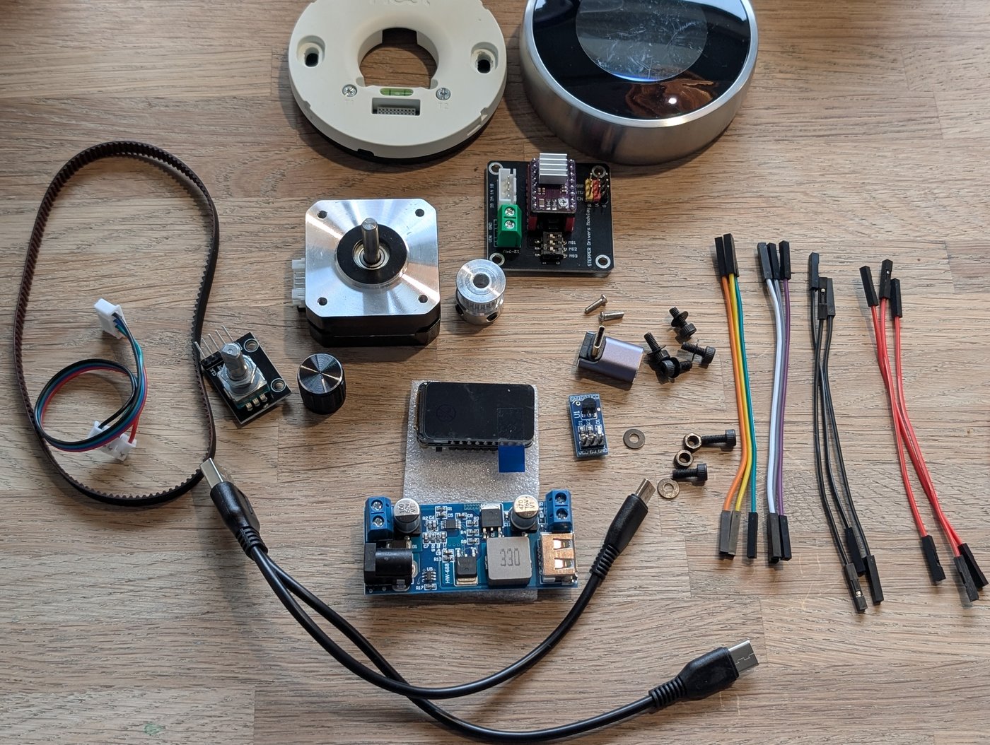
01 — Parts & Tools
Gather all parts and tools before you start. Check the list below.
Tools required
| Component | Description | Qty |
|---|---|---|
| ESP32-C6 LCD 1.47 | ESP32-C6 dev board with 1.47" Waveshare display | 1 |
| DRV8825 Stepper Driver | Microstepping driver module (heatsink included) | 1 |
| Stepper Driver Expansion Board | 4-channel driver carrier board | 1 |
| NEMA17 Stepper Motor | 1.8°, 17 Ncm, 1A, 23mm body length | 1 |
| DS18B20 Temperature Sensor | Digital 1-Wire temperature module | 1 |
| KY-040 Rotary Encoder | 360° encoder with push button | 1 |
| GT2 Belt 320mm | Closed loop 2GT-320-6mm belt | 1 |
| GT2 Pulley 20T | 20 teeth pulley, 5mm bore | 1 |
| 12V 3A Power Adapter | 5.5x2.1mm DC output adapter | 1 |
| DC-DC Buck Converter | 12V to 5V 5A step-down module | 1 |
| USB-C 90° Adapter | Power the ESP32 | 1 |
| 12V Power Cable (thick) | 14cm red/black cable for stepper 12V supply | 1 |
| Dupont Jumper Wires pack | 10 cm Female to Female | 1 |
| 2 in 1 USB C - Micro USB Cable | 0.2m Split cable | 1 |
| Stepper Motor Cable | 10-15cm JST XH2.54mm female (black, green, blue, red) | 1 |
| M3x8 Screws | Metric screw, 8mm length | 8 |
| M3 Washers | M3 flat washer | 6 |
| M2x8 Screws | Metric screw, 8mm length | 2 |
| GT2 Pulley 138T 3D PRINT | Custom pulley for Nest thermostat | 1 |
| Mounting Plate 3D PRINT | Baseplate for electronics and Nest mounting | 1 |
| Stand 3D PRINT | Stand for the Mounting Plate | 1 |
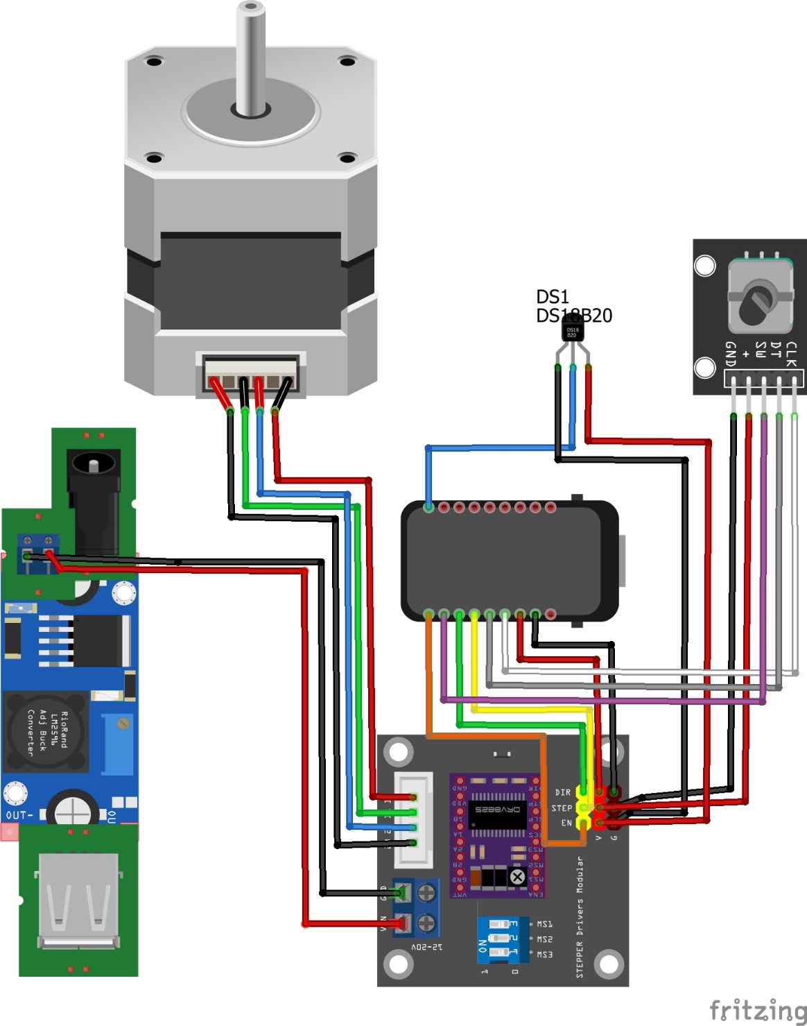
02 — Wiring Diagram
The steps below explain how to connect each component and which cables are needed. Below is a complete overview.
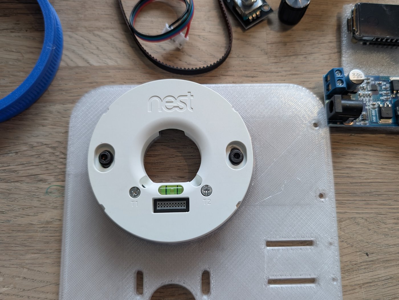
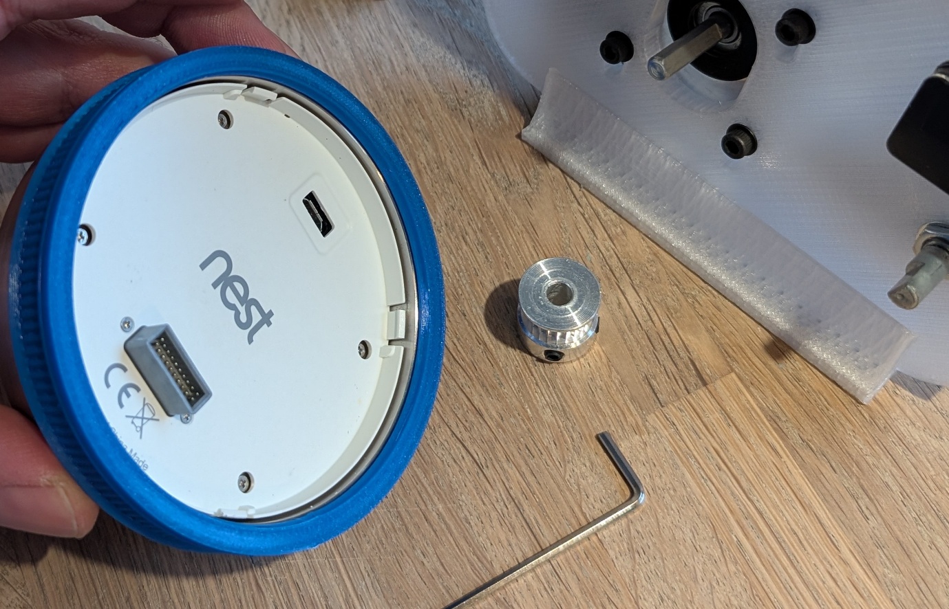
03 — Nest Baseplate
- Remove the outer front cover of the Nest, leaving only the Nest baseplate.
- The 3D-printed mounting plate has 2 oval protruding pieces with a hole in them.
- Place the Nest on top and secure it with 2 M3 bolts.
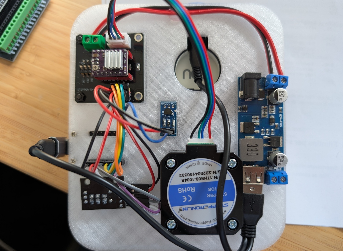
04 — Mounting Components on Baseplate
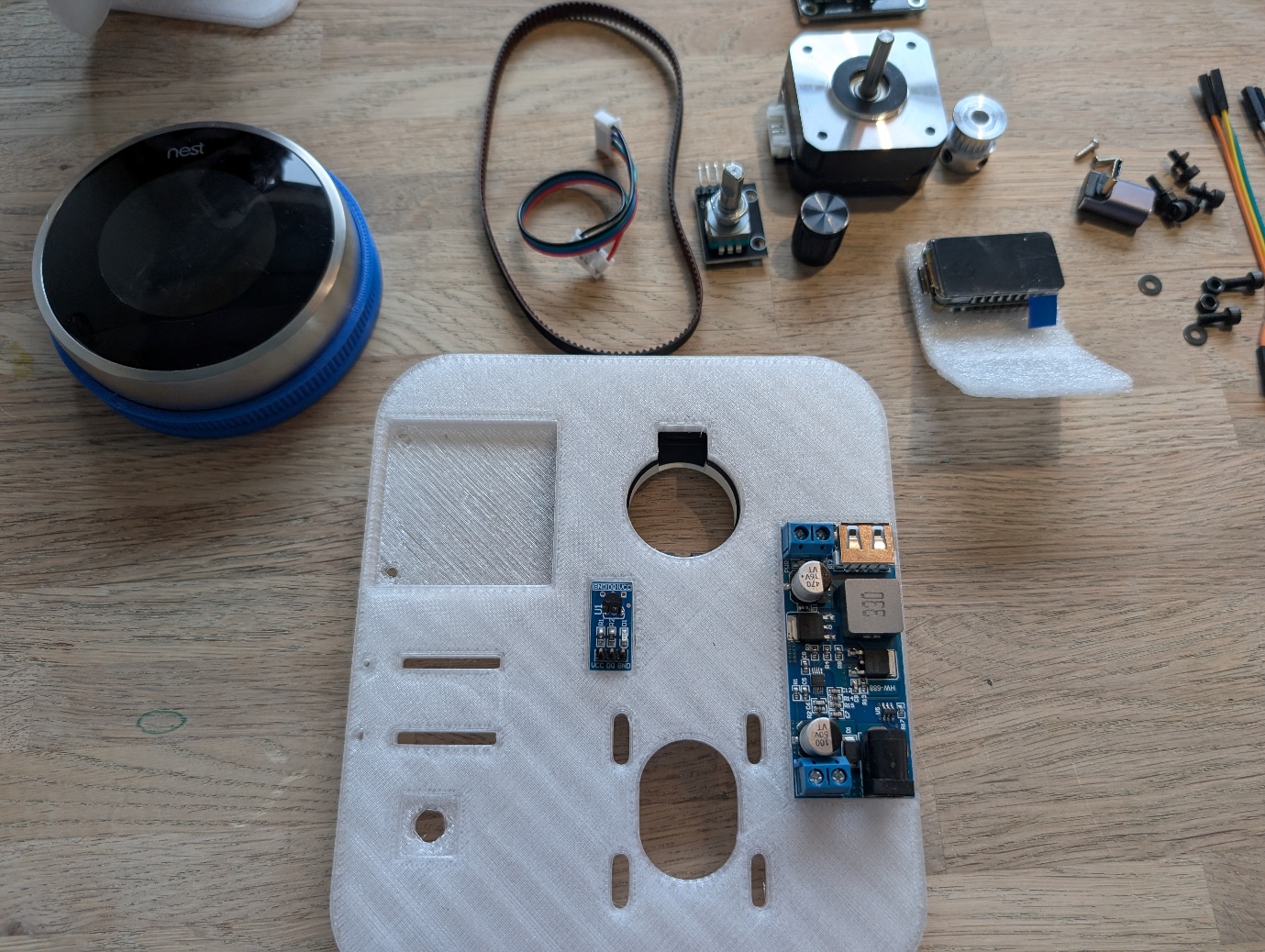
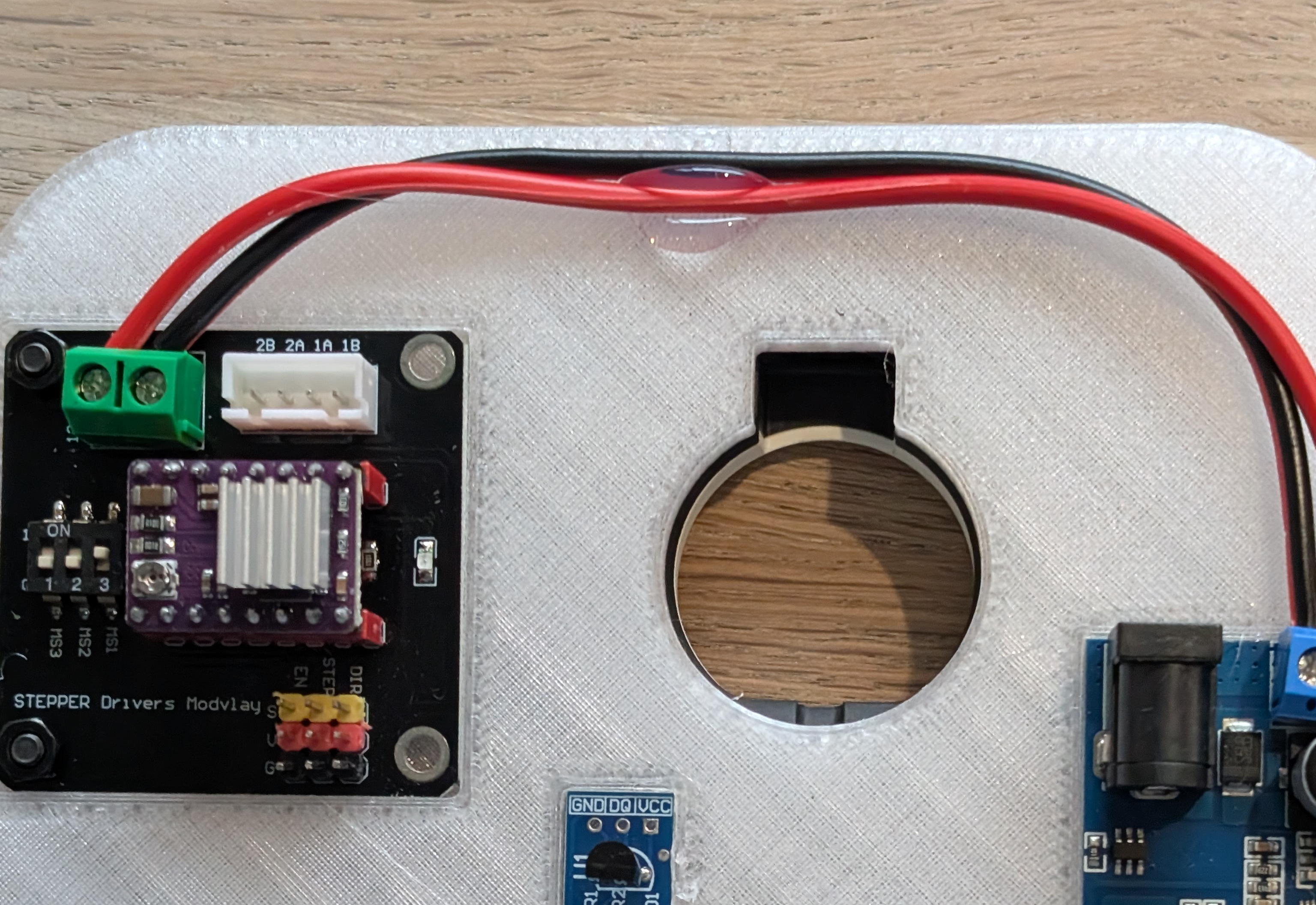
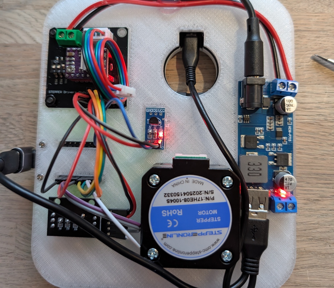
The white 3D-printed frame is the base on which all electronics are mounted. Place the frame flat in front of you.
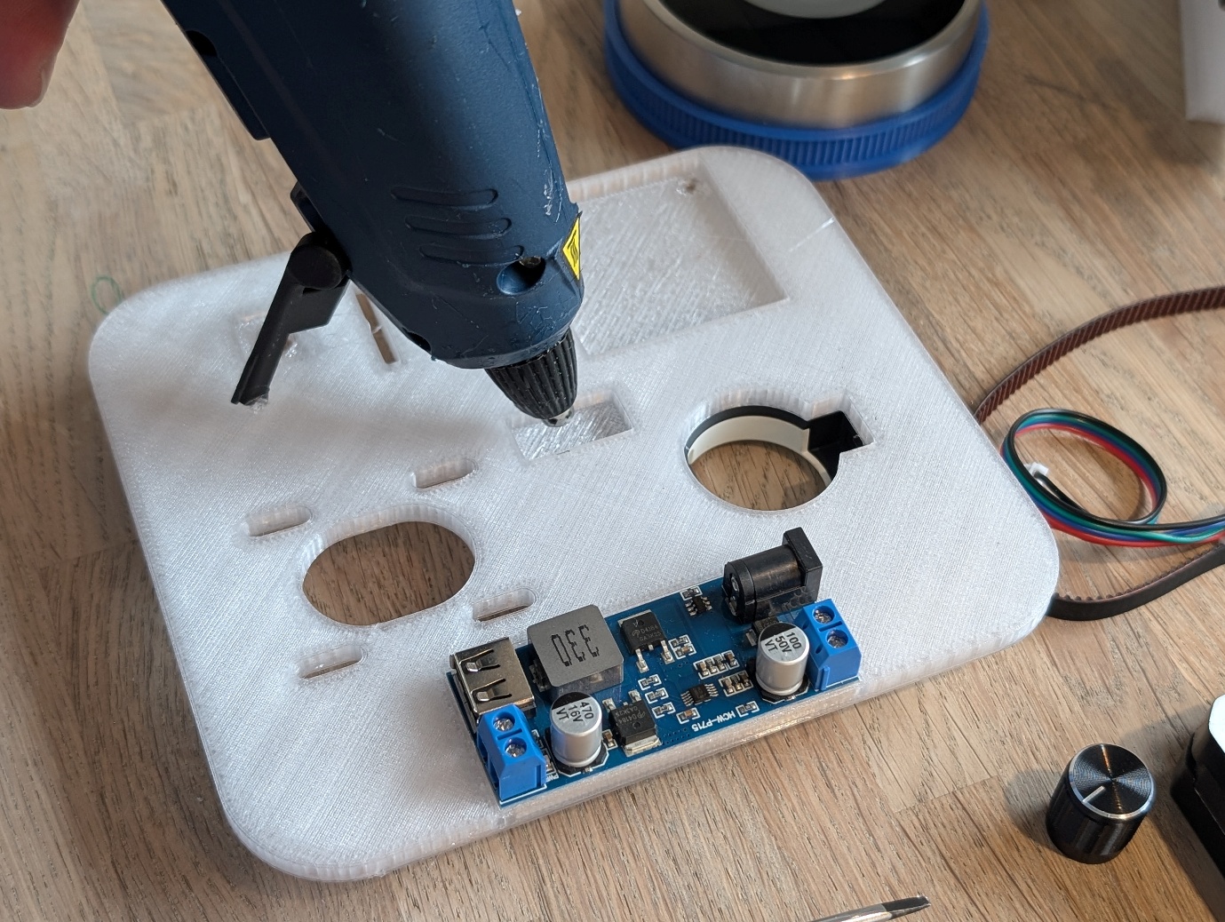
Buck Converter & Temperature Sensor
Place the DC-DC Buck Converter and the DS18B20 Temperature Sensor and secure them with hot glue.
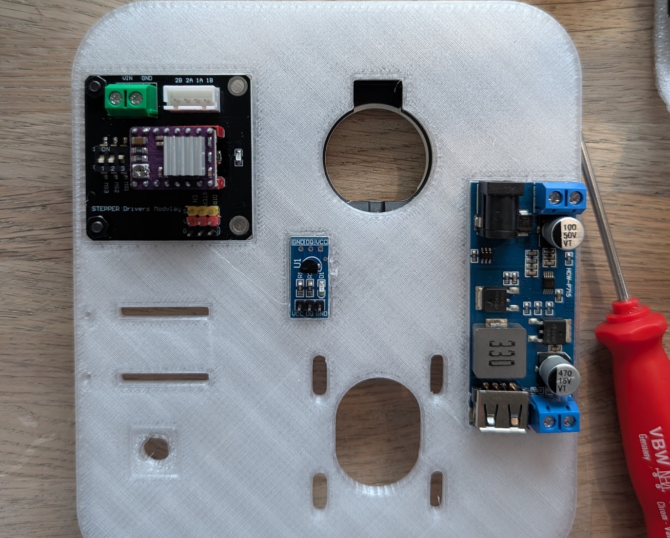
Stepper Driver Expansion Board
Mount the Stepper Driver Expansion Board and secure it with 2 bolts, 2 washers and 2 nuts. Make sure to place the DRV8825 Stepper Driver in the correct orientation on the expansion board. See photo.
12V Power Wires
Attach the 2 thicker wires (14cm) for positive and negative of the 12V stepper driver supply, and secure them at the top with hot glue.
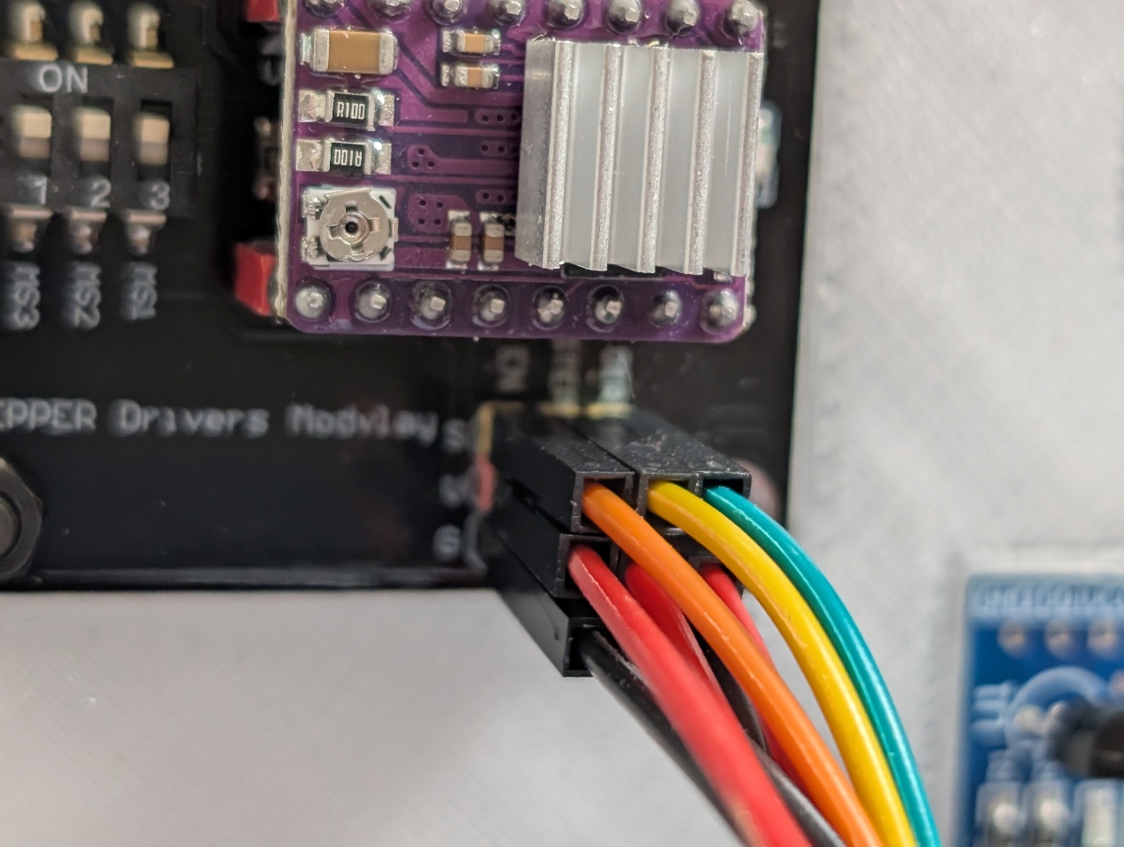
Jumper Cables — Stepper Driver Board
Before adding the other components, we start with the jumper cables. First, connect the jumper cables to the Stepper Driver Expansion Board.
Left: orange (EN), yellow (STEP), green (DIR). Below that 3 red jumper wires and at the bottom 3 black jumper wires.
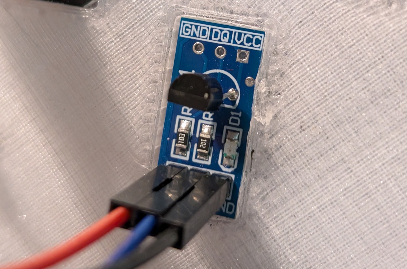
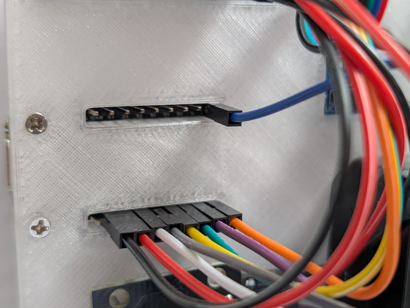
Jumper Cables — DS18B20 Temperature Sensor
Next, connect the jumper cables to the DS18B20 Temperature Sensor: Red (VCC), blue (DQ), black (GND).
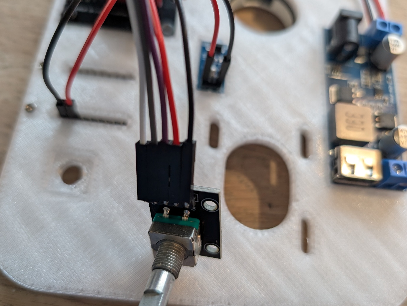
Jumper Cables — KY-040 Rotary Encoder
Now take the KY-040 Rotary Encoder and connect the jumper wires: Black (GND), red (VCC), purple (SW), grey (DT), white (CLK).
Mount ESP32-C6 & Connect Wires
Now mount the ESP32-C6 LCD 1.47. The USB port faces outward and is secured with M2x8 bolts. Then connect the jumper wires.
| Wire | ESP32 Pin | Connects to | Label |
|---|---|---|---|
| Black | GND | Stepper Driver Expansion Board | G |
| Red | 3V3 | Stepper Driver Expansion Board | V |
| White | 0 | KY-040 Rotary Encoder | CLK |
| Grey | 1 | KY-040 Rotary Encoder | DT |
| Yellow | 2 | Stepper Driver Expansion Board | STEP |
| Green | 3 | Stepper Driver Expansion Board | DIR |
| Purple | 4 | KY-040 Rotary Encoder | SW |
| Orange | 5 | Stepper Driver Expansion Board | EN |
| Blue | 9 | DS18B20 Temperature Sensor | DQ |
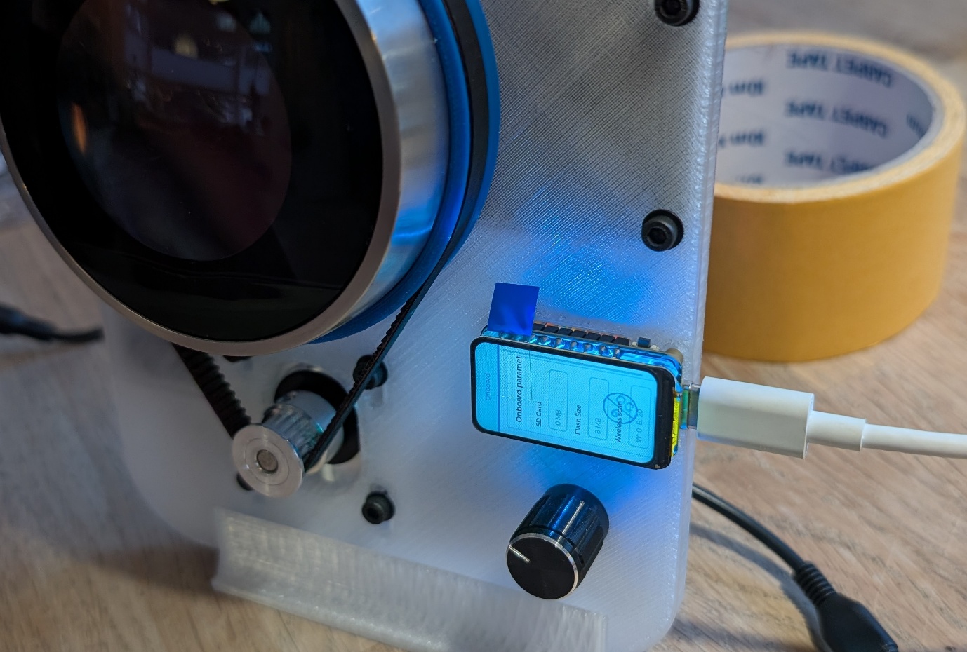
Power On Test
Now connect the USB cable to the ESP32 and plug the 12V adapter into the DC-DC Buck Converter. LEDs should now light up on the DC-DC Buck Converter, DS18B20 Temperature Sensor and Stepper Driver Expansion Board.
05 — Gears and Belt
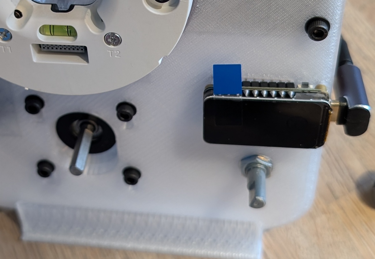
Mount the Stepper Motor
Flip the baseplate and mount the stepper motor. Use 4x M3x8 bolts and 4 M3 washers. Do not fully tighten the bolts so you can slide the stepper motor back and forth.
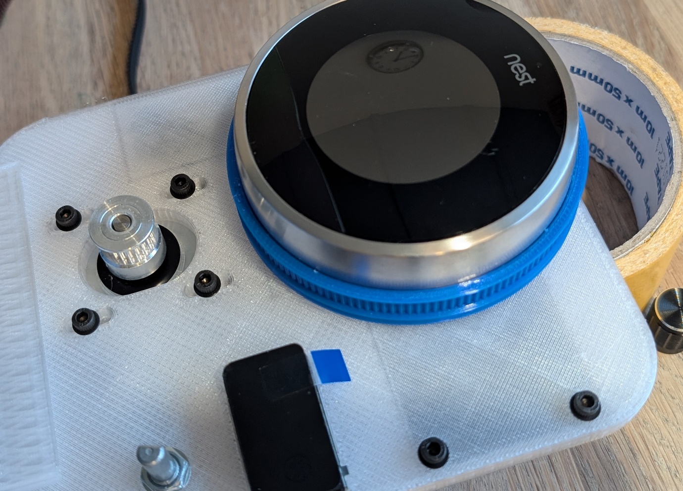
Attach the Large Gear to the Nest
Apply thin double-sided tape at 3 points on the large 3D-printed gear and press it onto the bottom of the metal Nest ring. Then place it onto the already mounted Nest wallplate.
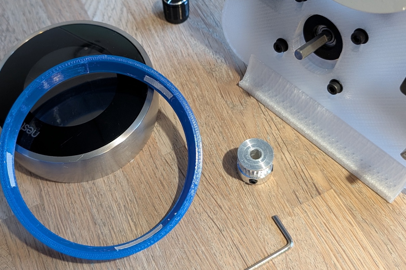
Mount the Pulley on the Stepper
Mount the pulley onto the stepper motor shaft using the hex key.
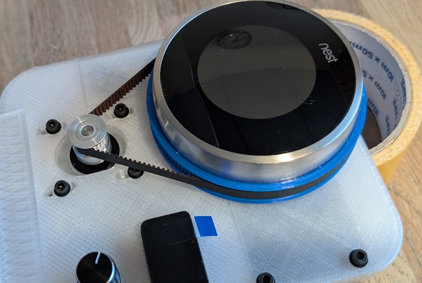
Install and Tension the Belt
Place the belt over both pulleys. The stepper motor needs to be slid upward for this. Once the belt is in place, carefully tension it by sliding the motor downward and tightening the bolts.
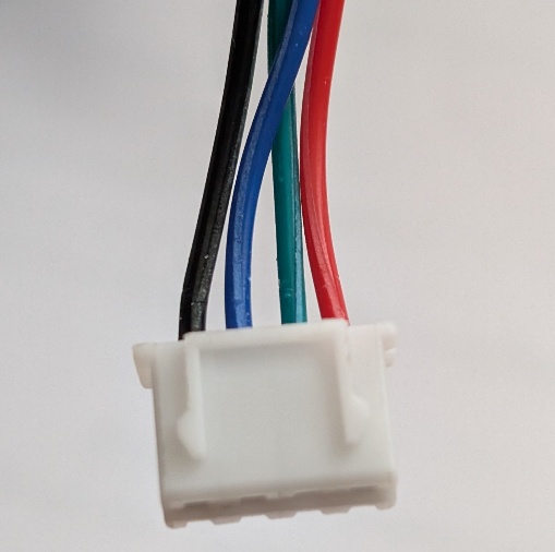
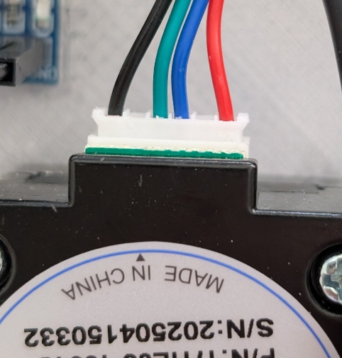
06 — Connecting the Stepper Motor
The stepper motor still needs to be connected to the Stepper Driver Expansion Board. The board is labeled 2b, 2a, 1a, 1b. The pin order may vary per motor. For this stepper motor, connect as follows:
The stepper motor has 6 connectors; the outermost and innermost ones are used.
Left: black · left middle: green · right middle: blue · right: red
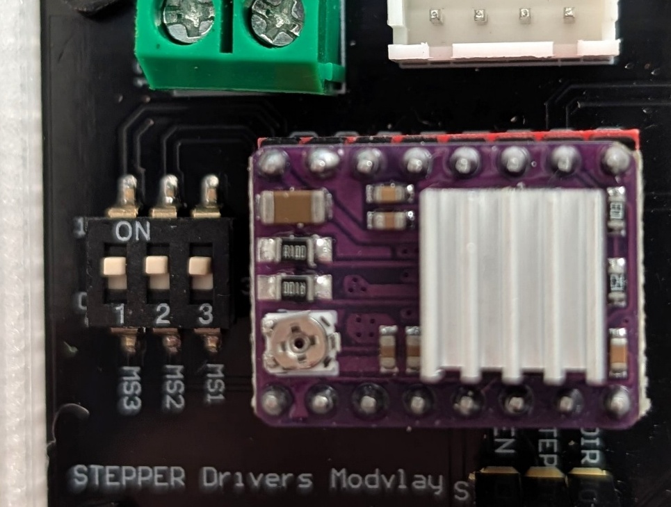
07 — Microstepping & Current Limiting
Microstepping
A standard NEMA17 motor has 200 steps per full revolution. With microstepping, the driver divides each step into smaller increments. At 1/32 microstepping, each step is split into 32 micro-steps, resulting in 6400 steps per revolution. This produces smoother and quieter movement.
Set the microstepping to 1/32 by setting all 3 mini jumpers to 1.
| MS1 | MS2 | MS3 | Microsteps |
|---|---|---|---|
| Low | Low | Low | Full step |
| High | Low | Low | Half step |
| Low | High | Low | 1/4 step |
| High | High | Low | 1/8 step |
| Low | Low | High | 1/16 step |
| High | Low | High | 1/32 step ← use this |
| Low | High | High | 1/32 step |
| High | High | High | 1/32 step |
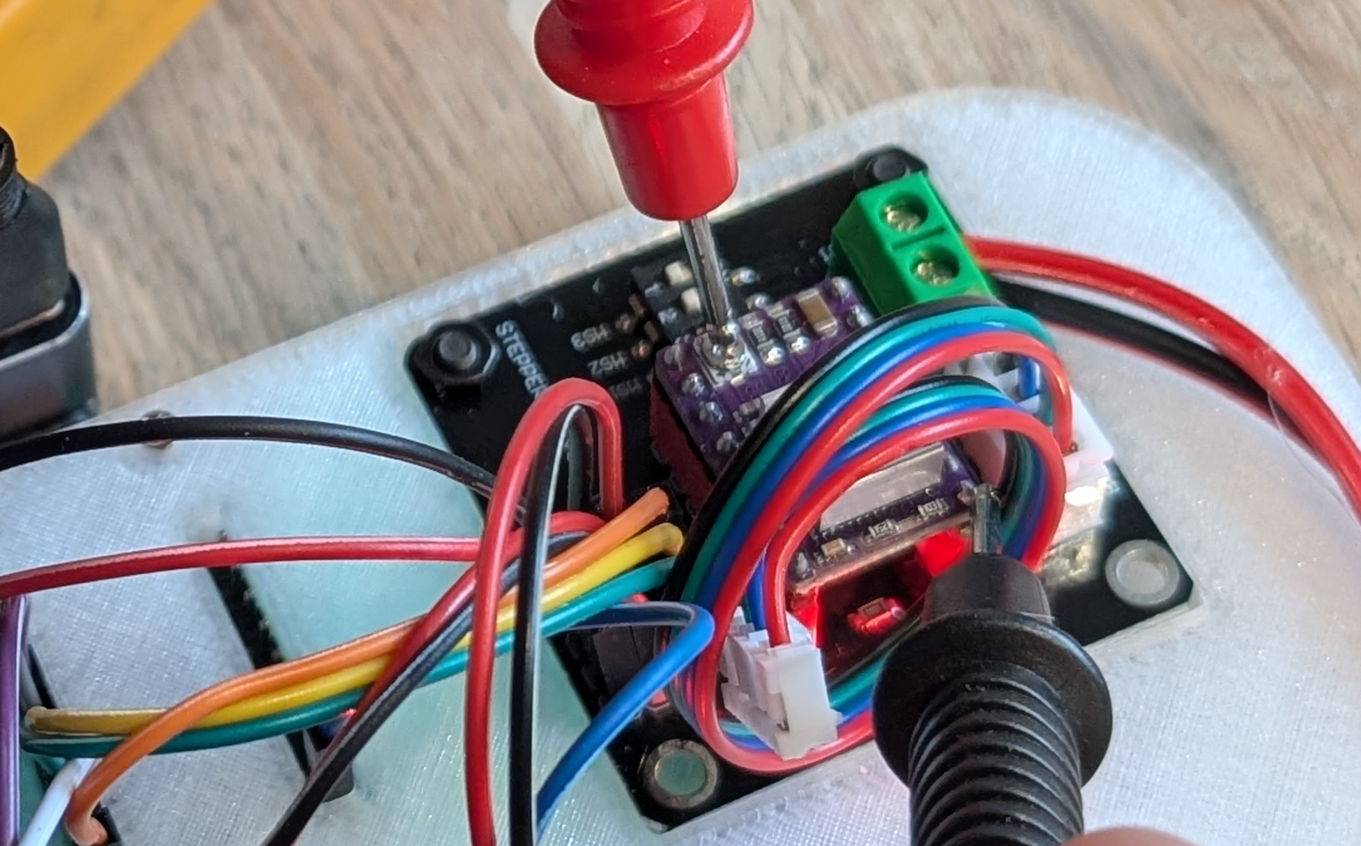
Current Limiting
The DRV8825 limits the current to the motor via an internal current-limiting circuit. You set how much current the motor receives via a small trimpot on the DRV8825.
Too little current = missed steps. Too much = overheating.
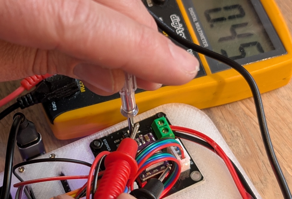
The rated current is printed on the label of your stepper motor (e.g. 1A or 1.5A). Set the current to 70–90% of this value.
Vref = (90% of 1A) × 0.5 = 0.45V
Make sure the system is fully powered on. Use a small Phillips screwdriver. When you hold the positive probe of your multimeter against the screwdriver and the negative probe on GND, you can see the current Vref live.
08 — Final Steps
Secure the Rotary Encoder
Before the firmware can be flashed to the ESP, the KY-040 Rotary Encoder must be secured. Simply insert it through the hole and tighten the ring and nut. Finally, press the knob onto the rotary encoder.
Final Cable Check
Then carefully check that all cables are connected and place the baseplate in the Stand.
Flash Firmware via USB
Connect the USB cable and go to nastythermostat.cc/webflash — then follow the steps in the webflasher to install the firmware.